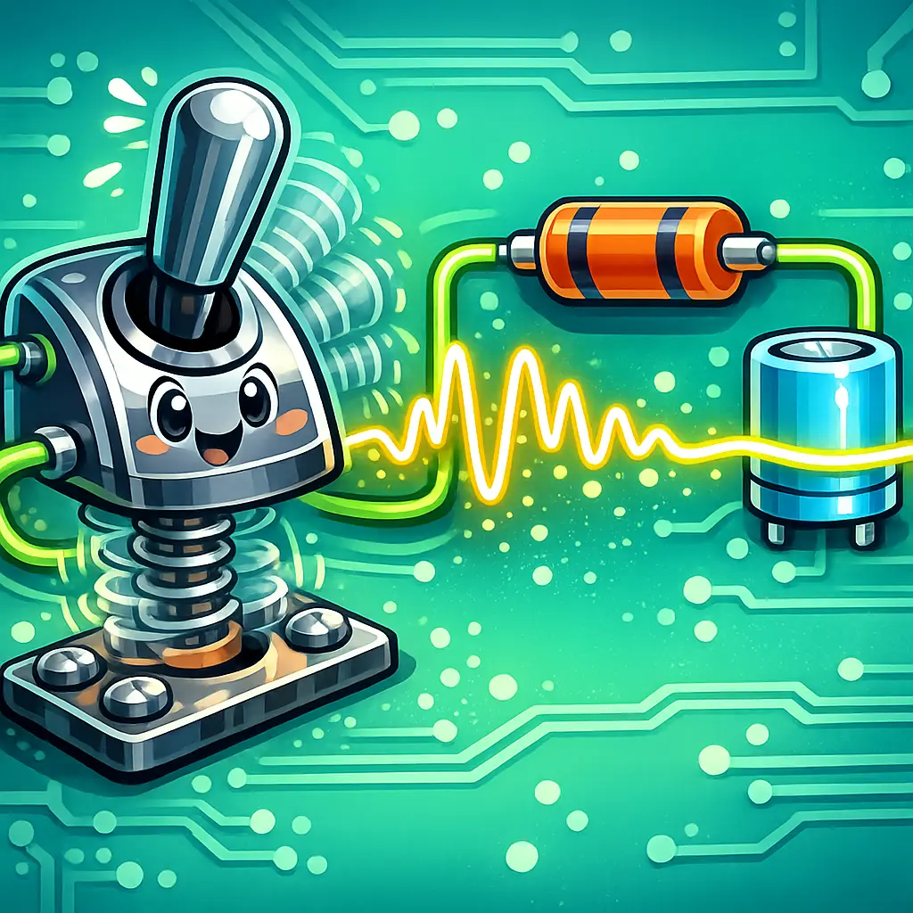
Switch modeling involves representing the behavior of electrical switches in circuit analysis, accounting for real-world imperfections. Contact bounce refers to the rapid, unintended making and breaking of contact when a switch is toggled, causing multiple unwanted signals. Debounce RC circuits use a resistor-capacitor network to filter out this noise, ensuring that only a single, clean transition is registered when the switch changes state, improving circuit reliability and accuracy.
Switch Modeling, Contact Bounce & Debounce RC
Switch modeling involves representing the behavior of electrical switches in circuit analysis, accounting for real-world imperfections. Contact bounce refers to the rapid, unintended making and breaking of contact when a switch is toggled, causing multiple unwanted signals. Debounce RC circuits use a resistor-capacitor network to filter out this noise, ensuring that only a single, clean transition is registered when the switch changes state, improving circuit reliability and accuracy.
💡 Key Takeaways
- Understand what switch contact bounce is and how it creates multiple fast transitions during a single press or release.
- Model a mechanical switch by including bounce behavior and non-ideal parasitics (contact capacitance/inductance) in circuit simulations.
- Learn how RC debounce circuits suppress bounce by smoothing rapid transitions into a clean digital edge.
- Analyze how the RC time constant and input thresholds determine debounce time and response speed.
- Apply practical guidelines to select RC values and pull-up/pull-down configurations for reliable debounce across different switches.
❓ Frequently Asked Questions
What is contact bounce and why is it a problem?
Contact bounce is the brief chatter of mechanical switch contacts when they open or close, causing rapid on/off transitions. This can confuse digital circuits and create false multiple presses unless debounced.
What is switch modeling and how does it help in circuits?
Switch modeling represents a real switch as time-varying resistance and delay, capturing bounce and make/break dynamics. It helps predict how a switch will affect circuit behavior before building the hardware.
What is a debounce RC circuit and how does it work?
An RC debouncer uses a resistor and capacitor to slow rapid transitions from a switch. The resulting output is filtered to remove bounce, and a Schmitt trigger or digital gate then provides a clean, sharp logic level.
How should you choose RC values for debouncing?
Select an RC time constant tau = R·C that is longer than the switch’s bounce period but short enough for your desired response time. For mechanical switches, typical tau ranges from about 1 ms to 10 ms; adjust R and C based on available input impedance and timing needs.